LED PCB

LED PCB

  • 1-6 layer Aluminum PCB & Other Metal Core PCB (MCPCB
  • Board Thickness:0.5 – 4MM
  • Copper Thickness: 1-4OZ
  • 2-3 Days Fast LED PCB Prototype
  • 7-10 Days Fast Production Lead Time for upto 100+m2/order
Content Table

What is LED PCB

Introduction of LED PCB

LED PCB is a kind of PCB that used for LED Lighting appliances. At present, it mainly uses metal based copper clad laminate with good heat dissipation function. Generally, the single panel is composed of three layers: circuit layer (copper foil), insulation layer and metal / Ceramic / FR4 as its substrate layer. 

The surface of the SMD LEDs are mounted on the circuit layer. The heat generated during the use of the LED appliance is quickly transferred to the substrate layer through the insulation layer, and then the heat is transferred out by the substrate layer, so as to realize the heat dissipation of the LED appliance.

As the most widely available metal, copper, iron and aluminum are considered as the commonly used metal thermal conductive layer materials. Iron core PCB is mainly used for motors and other high-end PCBs. 

Iron is harder than aluminum, so it’s more expensive to process as PCB substrate with iron, compares to aluminum and copper. As the thermal conductivity of iron is not as high as that of aluminum, most of the common LED PCB will not use iron as the base material. Copper and aluminum have better thermal conductivity. At present, LED PCB mainly uses these two materials to make metal thermal conductive layer. Because aluminum is cheaper and easier to form, it is used as the main LED PCB material. Copper has better thermal conductivity, but because of its higher cost, it is used as high-end LED PCB material, such as automotive headlamp led PCB. 

Working principle of LED PCB

The surface of the power device is mounted on the circuit layer, and the heat generated during the operation of the device is quickly transferred to the metal base layer through the insulation layer, and then the heat is transferred out by the metal base layer, so as to realize the heat dissipation of the device.


Figure 1: LED PCB Working principle

Structure of LED PCB

  • Circuit layer

The circuit layer (usually electrolytic copper foil) is etched to form printed circuit, which is used for the assembly and connection of components. Compared with the traditional FR-4 PCB, LED PCB substrate can carry higher current with the same thickness and line width.


  • Insulating layer

Insulating layer is the core technology of metal substrate for LED PCB, which mainly plays the functions of bonding, insulation and heat conduction. Metal substrate insulation is the largest thermal barrier in power module structure. The better the thermal conductivity of the insulation layer is, the more conducive to the diffusion of heat generated during the operation of the device, and the more conducive to reduce the operating temperature of the device, so as to improve the power load of the module, reduce the volume, prolong the life, and improve the power output.  


  • Metal Substrate Layer

What kind of metal is used for insulating metal substrate depends on the comprehensive consideration of thermal expansion coefficient, thermal conductivity, strength, hardness, weight, surface state and cost of the metal substrate.


Generally speaking, considering the cost and technical performance, aluminum plate is the ideal choice. There are 6061,5052,1060 aluminum plates available. Copper, stainless steel, iron and silicon steel plates can also be used if higher thermal conductivity, mechanical properties, electrical properties and other special properties are required.

Features of LED PCB substrate

LED PCB substrate, also known as metal core PCB substrate, including aluminum, copper, iron substrate mainly, is a low alloyed Al-Mg-Si type alloy substrate with high plasticity (structure see the figure below). It has good thermal conductivity, electrical insulation and mechanical processing performance. LED PCB substrate, in comparison with the traditional FR-4, with the same thickness and wire width, LED PCB substrate can carry a lot higher current. The withstand voltage of the aluminum substrate can reach 4500V, and the thermal conductivity is greater than 2.0kw/m.k. So LED substrate is mainly used in the industry that requires:

Comparison of current carrying capacity between aluminum substrate and FR-4 copper foil


  • Using surface mount technology(SMT)
  • Very effectively dealing with the thermal diffusion in the circuit design scheme
  • Reduce the operating temperature of the product, improve the power density and reliability of the product, and extend the service life of the product
  • Reduce product volume and hardware and assembly costs
  • Replacing fragile ceramic substrate for better mechanical durability

LED Storage Conditions

After the production of LED PCB is completed, it is generally packaged in vacuum and stored in a dark and dry environment. The pads of the LED PCBs are susceptible to moisture and oxidation, resulting in poor welding during SMT. It is suggested that led lighting manufacturers should complete SMT welding within 48 hours after opening PCB vacuum packaging.

7 Design Suggestions for Better LED PCB Performance

  1. The higher the power density of the module, the better the thermal conductivity and the lower the thermal resistance


  1. The larger the current carrying capacity is, the thicker the conductive layer (copper foil) of aluminum substrate is


  1. The insulation breakdown voltage of aluminum substrate should meet the requirements of insulation performance of module electrical appliances


  1. A minimum insulation barrier must be maintained between the edge of the circuit board (or a hole in the circuit board) and the nearest conductor, generally material thickness + 0.5mm


  1. In the process of drilling, punching, cutting and other mechanical processing of aluminum substrate, attention should be paid not to break or contaminate the insulating thermal conductive layer close to the conductor


  1. The bending, twisting and flatness of Aluminum Based PCB are affected by the structure and quality of punching, cutting and other machining tools. In addition, the bending effect caused by the different expansion coefficient between the circuit layer, the insulating thermal conductive layer and the metal base should be considered. The effect is determined by the ratio of the thickness of the conductive layer (copper foil) to the metal substrate (aluminum plate). The greater the ratio, the greater the bending degree. If the thickness of copper foil is less than 10% of the thickness of metal base, the metal base (aluminum plate) will dominate the mechanical properties, and the flatness of PCB is also satisfactory. If the thickness of the copper foil exceeds 10% of the thickness of the metal base, the PCB structure will be bent.


  1. Due to the difference of the expansion coefficient between the circuit layer (copper foil) and the metal substrate, the aluminum based PCB will always have a certain degree of bending. If the circuit is narrow enough, the stress caused by the expansion coefficient will be offset by the thermal insulation layer without deformation. The heat dissipation of metal substrate will directly affect the luminous flux and life of high brightness LED.

LED PCB Testing Points

  • Appearance: delamination and blistering
  • Insulation thickness
  • Thickness of metal plate
  • performance parameter
  • peel strength
  • Solder resistance
  • Electrostatic breakdown voltage
  • Thermal resistance
  • Impedance
  • Thermal conductivity
  • Surface resistance
  • Volume resistance
  • Dielectric constant
  • Dielectric loss
  • Fire resistance

Different Types of LED PCB

Introduction of common LED PCB Types

FR4 Printed Circuit Board (FR4 PCB)

FR4-LED-PCB
FR4-LED-PCB

FR4 printed circuit substrate has been commonly used for LED PCB for a long while. Its heat conductivity is 0.36w/m.k, and the thermal expansion coefficient is 13 ~ 17ppm / K. It can be single-layer or multi-layer copper foil design. 

Advantages: mature technology, low cost, can be used in large-size panels. 

Disadvantages: poor thermal performance, generally used in traditional low power LED.

Metal Core Printed Circuit Board (MCPCB)

LED PCB - AL PCB Black Solder Mask
LED PCB – AL PCB Black Solder Mask

Due to the poor thermal conductivity and thermal efficiency of FR4 PCB, it is only suitable for the traditional low wattage LED light. Therefore, the PCBs were later attached to a metal substrate, which is the so-called metal core PCB. MCPCB is made of copper clad laminate (also known as insulating metal substrate) by the regular printed circuit manufacturing processes.


According to the different metal substrates used, it can be divided into copper core LED PCB, aluminum core LED PCB, and iron core LED PCB.

Advantages of MCPCB

(1) Heat dissipation

The Advantages of Metal Core Printed Circuit Boards | FastPCBUnion.com
The Advantages of Metal Core Printed Circuit Boards

Conventional PCB substrate such as FR4 is with a poor thermal conductor, insulation between layers, heat can not be emitted. Metal core LED PCB substrate can solve this heat dissipation problem more efficiently.


(2) Thermal expansion

LED PCB Material Thermal Conductivity & CTE - FastPCBunion.com
LED PCB Material Thermal Conductivity & CTE

CTE (coefficient of thermal expansion) of different materials is different. The CTE of PTH hole wall and insulation wall in PCB is very different in Z axis, so the heat generated can not be eliminated in time. Thermal expansion and contraction may lead to PTH cracking or even disconnection. Metal based printed circuit board can effectively solve the problem of heat dissipation, so as to alleviate the thermal expansion and cold contraction of different components on the printed circuit board, and improve the durability and reliability of the whole machine and electronic equipment.

(3) Dimensional stability

MCPCB, obviously, is much more stable than FR4 PCB. Al PCB is heated from 30 ℃ to 140 ~ 150 ℃, and the size change is only 2.5 ~ 3.0%. The structure of MCPCB is composed of three layers of different materials: copper, insulating layer and metal substrate (copper, aluminum and iron). Aluminum based copper clad laminate is the most common metal substrate.

(4) Higher Solder Joint Strength after long use

Soldering Strength MCPCB vs FR4 PCB - FastPCBUnion.com
Soldering Strength MCPCB vs FR4 PCB

This figure shows the % drop in shear strength. This can be explained keeping in mind the physical properties of the test board materials and LED package substrate. During temperature cycling the solder joints experience cyclic stress in the lateral direction due to CTE mismatch between the circuit board material and the LED sub-mount material. As shown in table I, the CTE of FR4 is 17 ppm/K and Aluminum is 25 ppm/K while that of Al2O3(LED substrate) is 7ppm/K. Therefore, the CTE mismatch for LEDs assembled on FR4 boards is 10ppm/k while those assembled on MCPCB-MP boards is 17ppm/k. Therefore, the solder joints in LEDs on MCPCB will experience much higher stress during temperature cycling as compared to those assembled on FR4 boards. In addition to CTE mismatch, modulus of the materials involved also plays a key role. While solder joint is experiencing a cyclic stress during temperature cycling if the circuit board material is soft (have low modulus), it will tend to deform first which will in turn reduce stress at the solder joint. FR4 has relatively lower modulus than Aluminum, therefore, stress on the solder joints of LEDs on FR4 boards will still be lower. That also further explains almost no drop in shear strength of the LEDs on FR4 boards. As seen in Figure 7, 

Technical characteristics of MCPCB

(1) Thinner the insulation layer is, the lower thermal resistance is

(2) High mechanical strength

(3) Standard size: 500 × 600mm

(4) Standard size: 0.8, 1.0, 1.2, 1.6, 2.0, 3.0 mm

(5) Copper foil thickness: 18um, 35um, 70UM, 105um

Ceramic Printed Circuit Board (Ceramic PCB)

Ceramic PCB - FastPCBunion.com
Ceramic PCB

Ceramic material is used as LED packaging substrate, which has insulation, no dielectric layer, good thermal conductivity and thermal expansion coefficient (4.9 ~ 8ppm / k), which matches with LED chip, Si substrate or sapphire, and will not generate thermal stress and thermal deformation due to heat.

A typical ceramic substrate, such as AIN, has a thermal conductivity of about 170 ~ 230W / m.k and a thermal expansion coefficient of 3.5 ~ 5ppm / K. The price is relatively expensive, and the size is limited to 4.5 square inches. It can not be used in the large-area panel. It is suitable for high power LED in high-temperature environment.

Comparison of thermal properties between AlN ceramic substrate and other materials - FastPCBunion.com
Comparison of thermal properties between AlN ceramic substrate and other materials

AlN ceramic substrate has good thermal conductivity, and the coefficient of thermal expansion led chip (CTE = 5ppm / k) is well matched.


Direct Copper Bond Ceramic PCB (DCB PCB)

Direct copper bond ceramic substrate is a kind of PCB copper-clad laminate which is made by sintering copper foil directly on the ceramic surface using DCB (direct copper bond) technology. 

An optimal structural design to improve the reliability of Al2O3–DBC substrates under thermal cycling
DCB layer structure


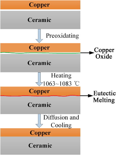
Direct copper bond ceramic substrate has excellent thermal cycling, stable shape, good rigidity, high thermal conductivity and high reliability. The copper coated surface can be etched with various patterns. Moreover, it is a pollution-free and pollution-free green product. It can be used from – 55 ℃ to 850 ℃ and its thermal expansion coefficient is close to that of silicon. It is widely used in semiconductor refrigeration Many industrial electronic fields, such as electronic heater, high-power power semiconductor module, power control circuit, power hybrid circuit, intelligent power module, high-frequency switching power supply, solid-state relay, automotive electronics, aerospace and military electronic components, solar panel components, telecommunication special exchange machine, receiving system, laser, and other industrial electronic fields.


Advantages of DCB Technology: there are many ways to realize metal-ceramic bonding. The effective alloying methods widely used in industry are the thick film method and the molybdenum manganese method. The thick film method is composed of fine particles of precious metals by pressing together, and then the fused glass adheres to the ceramic, so the conductivity of the thick film is worse than that of copper. Although the molybdenum manganese method makes the metal layer have relatively high conductivity, the thickness of the metal layer is often very thin, less than 25 μ m, which limits the surge resistance of high-power module components. Therefore, it is necessary to have a new method of cermet bonding to improve the conductivity of the metal layer and the ability to withstand high current and reduce the contact thermal resistance between the metal layer and the ceramic, and the process is not complicated. Copper ceramic direct bonding technology solves the above problems and creates a new trend for the development of power electronic devices.

Advantages of DCB PCB Substrate
  • The thermal expansion coefficient of DCB is close to that of silicon chip, which can save transition layer Mo sheet, save labor, material and cost;
  • Reduce welding layer, thermal resistance, cavity and increase yield;
  • Under the same current carrying capacity, the width of 0.3mm thick copper foil is only 10% of that of ordinary printed circuit board;
  • The excellent thermal conductivity makes the package of the chip very compact, which greatly improves the power density and improves the reliability of the system and device;
  • The ultra-thin (0.25 mm) DCB board can replace BeO without environmental toxicity;
  • The temperature rise is about 17 ℃ when 100A current continuously passes through a copper body with a width of 1 mm and a thickness of 0.3 mm, and a temperature rise of about 5 ℃;
  • The thermal resistance of 10 × 10 mm DCB plate is low:
  1. The thermal resistance of DCB with 0.63mm thickness is 0.31k/w
  2. The thermal resistance of 0.38 mm thick ceramic substrate DCB is 0.19 K / W
  3. The thermal resistance of 0.25 mm thick ceramic substrate DCB is 0.14 K / W
  • High insulation and withstand voltage to ensure personal safety and equipment protection capability;
  • New packaging and assembly methods can be realized to make the product highly integrated and reduce the volume.


The Most Common LED PCB Type: Aluminum Core LED PCB

Introduction of Aluminum Core LED PCB

LED PCB (7) - Fast PCB Union
LED PCB

Aluminum based LED PCB is composed of low alloyed Al Mg Si high plasticity alloy plate. It has good thermal conductivity, electrical insulation and machining performance. Compared with the traditional FR4 PCB, aluminum based LED PCB can carry higher current with the same thickness and line width. Aluminum based LED PCB can withstand voltage up to 4500V and thermal conductivity is more than 2.0. At present, aluminum based LED PCB is the most common one among various LED PCB applications.

Aluminum based LED PCB is generally a single panel, which is composed of three layers: circuit layer, insulation layer and metal base layer. Common LED PCB. There are top and bottom sides. The white side is welded SMD LED pin, and the other side is aluminum metal color. If there is a demand for high-power heat dissipation, the aluminum base can also be coated with thermal conductive silicone grease to coordinate with the installed radiator/heatsink.

Aluminum PCB Classification

1、 Traditional aluminum PCB
Traditional aluminum PCB is a hard PCB made of aluminum plate, insulating layer, and the conductive layer.
According to the manufacturing process, aluminum PCB can be divided into: tin spraying aluminum PCB, oxidation-resistant aluminum PCB, silver plating aluminum PCB, immersion gold aluminum PCB, etc.

COB Aluminum  PCB - FastPCBunion.com
COB Aluminum PCB

According to the appliances, aluminum PCB can be divided into: street lamp aluminum PCB, fluorescent lamp aluminum PCB, LB aluminum PCB, COB aluminum PCB, packaged aluminum PCB, bulb lamp aluminum PCB, power supply aluminum PCB, automobile aluminum PCB, etc.

2、 Flexible aluminum PCB
One of the latest developments of IMS materials is flexible dielectrics. These materials provide excellent electrical insulation, flexibility, and thermal conductivity. When applied to flexible aluminum materials such as 5754 or similar, products can be formed to achieve various shapes and angles, which can eliminate expensive fixtures, cables, and connectors. Although these materials are flexible, they are designed to bend into place and remain in place.

3、 Mixed aluminum PCB
In the “hybrid” IMS structure, the “sub-assemblies” of nonthermal materials are treated independently, and then Amitron hybrid IMS PCBs are bonded to the aluminum substrate with thermal materials. The most common structure is a 2-layer or 4-layer sub-assembly made of traditional FR4. Bonding this layer to an aluminum substrate with a thermoelectric medium can help heat dissipation, improve rigidity, and act as a shield. Other benefits include:
      a. It’s cheaper than building all the heat-conducting materials.
      b. Provides better thermal performance than standard FR-4 products.
      c. Expensive radiators and associated assembly steps can be eliminated.
      d. It can be used in RF applications requiring RF loss characteristics of PTFE surface layer.
      e. The use of component windows in aluminum to accommodate through-hole assemblies allows connectors and cables to pass connectors through the substrate while welding fillets to create a seal without the need for special gaskets or other expensive adapters.

4、 Multilayer aluminum PCB
In the high-performance power market, multi-layer IMS PCB is made of multilayer thermal conductive dielectrics. These structures have one or more layers of circuits embedded in dielectrics, and blind holes are used as thermal through holes or signal paths. Although it is more expensive and less efficient to transfer heat in a single layer design, they provide a simple and effective cooling solution for more complex designs.

5、 Through-hole aluminum PCB
In the most complex structures, a layer of aluminum can form the “core” of a multilayer thermal structure. Prior to lamination, aluminum is electroplated and dielectric-filled. Thermal materials or subassemblies can be laminated to both sides of the aluminum using a thermal bonding material. Once laminated, the finished component is similar to the traditional multilayer aluminum substrate through drilling. Electroplated vias pass through gaps in aluminum to maintain electrical insulation. Alternatively, copper cores may allow direct electrical connections and insulated through holes.

Common LED PCB Aluminium Substrate Datasheet Table

Material TypeTgProductManufacturerDatasheet
Aluminium130T-111TotkingView
Aluminium130TCB-2 (TCB-2AL)PolytronicsView
Aluminium17092MLArlonView
Aluminium185HPL-03015BergquistView
Aluminium105T-Lam 6061+ 1KA10LairdView
Aluminium120KW-ALEKinwongView
Aluminium140DST-5000DoosanView
Aluminium140T-Lam 5052 + 1KA04LairdView
Aluminium170VT-4A2VentecView
Aluminium105ML1KALairdView
Aluminium105SS1KALairdView
Aluminium105T-Lam – Alco 6061+1KA04LairdView
Aluminium105TLam SS 1KA06LairdView
Aluminium110TCP-1000BergquistView
Aluminium120KW-ALSKinwongView
Aluminium130CML-11006BergquistView
Aluminium130IT-859GTAITEQView
Aluminium130SA115ShengyiView
Aluminium130SA120ShengyiView
Aluminium130TCB-2LPolytronicsView
Aluminium140SAR15Shengyi View
Aluminium140SAR20ShengyiView
Aluminium140TCB-4PolytronicsView
Aluminium140TCB-8PolytronicsView
Aluminium145EPA-M2EastPowerView
Aluminium150HT-04503BergquistView
Aluminium150HT-07006BergquistView
Aluminium150HT-09009BergquistView
Aluminium165SSLLDLairdView
Aluminium168SSHTD04LairdView
Aluminium168SSHTD06LairdView
Aluminium17092ML DielectricArlonView
Aluminium170VT-4A1VentecView
Aluminium90LTI-04503BergquistView
Aluminium90LTI-06005BergquistView
Aluminium90MP-06503BergquistView

Aluminum Material Selection for Aluminum Core LED PCB

There are mainly 1000 series, 5000 Series and 6000 series aluminum based plates in common use. The basic characteristics of these three series aluminum materials are as follows:

Aluminum plate for LED PCB - FastPCBunion.com
Aluminum plate for LED PCB

① 1000 series (typical models – 1050, 1060, 1070)
1000 series aluminum plate is also known as pure aluminum plate. In all series, 1000 series aluminum content is the most, and the purity can reach more than 99.00%. Because it does not contain other technical elements, the production process is relatively simple and the price is relatively cheap. It is the most commonly used series in conventional industries. Most of the 1050 and 1060 series are in circulation on the market. 1000 series aluminum plate is based on the last two digits to determine the minimum aluminum content of this series. For example, the last two digits of 1050 series are 50. According to the international brand naming principle, its aluminum content must reach 99.5%, and the top is the qualified product. In China’s aluminum alloy technical standard (GB / t3880-2006), the aluminum content of 1050 is 99.5%. In the same way, the aluminum content of 1060 series aluminum plate must reach more than 99.6%.

② 5000 Series (typical models – 5052, 5005, 5083, 5A05 Series)
5000 series aluminum plate belongs to the common alloy aluminum plate series, the main element is magnesium, the magnesium content is between 3-5%, which is also known as aluminum magnesium alloy. Its main characteristics are low density, high tensile strength and high elongation. In the same area, the weight of aluminum magnesium alloy is lower than other series, so it is often used in aviation, such as aircraft fuel tank. In addition, it is widely used in conventional industry. Its processing technology is continuous casting and rolling, belonging to the hot rolling aluminum plate series, so it can do oxidation deep processing. In China, 5000 series aluminum plate is one of the more mature aluminum plate series.

③ 6000 Series (typical model- 6061)
6061 is a cold-treated aluminum forging product, which is suitable for applications with high requirements of corrosion resistance and oxidation resistance. Good usability, excellent interface characteristics, easy coating and good processability.
The general characteristics of 6061: excellent interface features, easy coating, high strength, good usability and strong corrosion resistance. Typical uses of 6061 aluminum: aircraft parts, camera parts, couplers, ship accessories and hardware, electronic accessories and joints.
In general, considering the texture, hardness, elongation, chemical properties and price of the material itself, 5052 alloy aluminum plate is commonly used in aluminum based LED PCB.

Advantage of Aluminum Core LED PCB

  • Meet ROHS requirements;
  • It is more suitable for SMT process;
  • In the circuit design scheme, the thermal diffusion is treated effectively to reduce the operating temperature of the module, prolong the service life, and improve the power density and reliability;
  • Reduce the assembly of radiator and other hardware (including thermal interface materials), reduce product volume, and reduce hardware and assembly costs;
  • The power circuit and control circuit are optimized;
  • Replace the fragile ceramic substrates for better mechanical durability

Disadvantage of Aluminum Core LED PCB

  • The cost is high. (At FastPCBunion.com, we could help you reduce the cost, and make sure that switch from FR4 to Aluminum PCB would not cost you any extra for your LED appliances.)
  • At present, the design of Aluminum PCB is mainly limited to 1-2 layer board, due to the mainstream manufacturing capability.
  • It is easy to have problems in electrical strength and withstand voltage. (At FastPCBunion.com, we have resolved the problem)

Suitable Applicances for Aluminum PCB

LED lighting products

Currently, aluminum PCB has been widely using for lighting PCB, especially LED PCB. Besides lighting appliance, there are main other senarios that are suitable for Aluminum PCB.

Audio equipment
Input, output amplifier, balanced amplifier, audio amplifier, pre-amplifier, power amplifier, etc.

Power supply equipment
Switch regulator ` DC / AC converter ` SW regulator, etc.

Communication electronic equipment
High frequency amplifier ‘filter electrical’ transmitting circuit.

Office automation equipment
Motor driver, etc.

Automobile
Electronic regulator, igniter, power controller, etc.

Computer
CPU board, floppy disk driver, power supply device, etc.

Power module
Converter, solid-state relay, rectifier bridge, etc.

Fast PCB Union - The LED PCB Manufacturer


Fast PCB Union Co. LTD has been focusing on LED PCB manufacturing for 10+ year. 

Our LED PCB products including Aluminum PCB & MCPCB (Metal core PCB, mainly Copper core PCB) & normal FR4 PCB  for Lighting / LED. Our PCBs are widely used in Automotive LED light, Street LED lights , Lawn LED lamp, Tube LED lights, Panel LED lights, Spotlights, Down lights, Commercial LED lights, Home LED lights, Energy saving LED lights and etc.


Our Technical Capability

Technical

 Object

Capability & specification

Material

Aluminum substrate / copper substrate / copper aluminum composite plate /FR-4

Thermal conductivity

1.0W/1.5W/2.0W/122W

Thickness

0.3~5.0MM

Surface Finishing

Lead-free HASL / Immersion Gold /OSP

Max. Panel size

1500*500MM

Min. Panel size

5*5MM

Min line width

0.25MM (10mil)

Min line gap

0.25MM (10mil)

Minimum aperture

∮1.6mm

E-T Test

100% Automated short circuit test

Technical

Object

Capability & specification

Plate warp rate

<=0.5% (350*350mm)

Withstand voltage

AC1500-4000V

Copper Foil Thickness

18um / 35um / 70um / 105um

Molding method

CNC /Die punching/ V-CUT

External tolerance

CNC: ±0.1~0.15MM

Die punching:±0.125MM

Type of resistance welding

White or customized

Production process

Exposure process

Monthly capacity

20000 square meters

Lead Time

Sample: 2-4 days / batch: 1~3 weeks.

Your Cost-Effective LED PCB Supplier in China


Fast PCB Union has been proudly servicing LED PCB needs in China and Globally among the cutting-edge materials. Accordingly to your appliances & budget, we will provide you the best option from the market available LED PCB substrate materials to produce your LED PCB in the most cost-effective manner.

At present, LED PCB mainly uses aluminum core substrate. The main purpose is that the aluminum substrate has good heat dissipation. Due to the high heat output of SMD LED beads, most of the PCB used for LED lighting use aluminum substrate as the production material.

When the heat dissipation power of aluminum substrate can not meet the requirements, copper core PCB gradually becomes a new widely used LED PCB material. The cost of copper core PCB is higher than that of aluminum substrate. But the cooling effect is better. In some lighting products that can bear the cost, such as automotive LED headlights, copper substrate began to gradually replace aluminum substrate and become the main automotive Lighting LED PCB substrate material.

FR-4 PCB is a traditional circuit board substrate material for most of the electronic products, because of its good insulation, corrosion resistance, compression resistance, multilayer printing and other characteristics. In the early stage, due to the cost reasons, FR-4 PCB was often used as the production material of LED circuit board. However, with the continuous decline of aluminum substrate cost and the demand of more and more high-power SMD LED mounting on PCB, FR-4 PCB has been gradually no longer used in LED PCB.

At Fast PCB Union, we will consider your product grade & market to suggest the most suitable PCB type for your best option

LED PCB Production process

Led PCB usually has good thermal conductivity, electrical insulation and machining performance. It is mainly made of metal clad copper plate, conductive layer and insulating layer. Led PCB is generally divided into single side PCB, double-sided PCB and multilayer PCB. At present, single side and double-sided PCB are mainly used in LED lighting industry. Metal substrate materials are generally more expensive, so it is necessary to pay attention to the standardization of the manufacturing process of LED PCB.

1、 Process flow of single-side LED PCB
Board cutting → prebake → drilling → drilling inspection → line layer dry film optical imaging → line layer inspection → etching → etching inspection → solder resist ink → character → solder resist ink layer inspection → tin spraying → metal base surface treatment → punching profile → electrical testing → FQC → packaging → shipping.

2、 Process flow of double-sided LED PCB
Board cutting → prebake → drilling → resin plug hole → QC inspection → surface roughening → pressing → drilling → drilling inspection → PTH copper plating → IPQC inspection → dry film optical imaging of line layer → line layer inspection → etching → stripping film → line layer inspection → solder blocking ink → surface treatment → characters → IPQC inspection → punching profile → electrical measurement → FQC → packaging → shipment

LED PCB Raw Material Cutting

(1) Cutting process: material preparation – cutting.
(2) The purpose of cutting material: to cut the large size incoming material into the size needed for production.
(3) Cutting precautions:
① Check the size of the first piece after cutting;
② Attention should be paid to aluminum surface and copper surface;
③ Pay attention to the delamination and edge of the plate edge.

LED PCB Drilling

(1) Drilling process: pin drilling inspection board.
(2) The purpose of drilling is to locate the plate and provide assistance for subsequent production process and customer assembly.
(3) Precautions for drilling:
① Check the number of boreholes and the size of empty holes;
② Avoid scraping of sheet metal;
③ Check the edge of aluminum surface and hole position deviation;
④ Check and replace the drill bit in time;
⑤ Drilling is divided into two stages: one is the peripheral tool hole after cutting material; the other is the tool hole in the unit after welding resistance welding.

Dry/Wet film imaging of circuit layer

(1) Dry / wet film imaging process: grinding circuit layer – sticking film – exposure – development.
(2) The purpose of dry / wet film imaging is to present the parts needed for making circuit on the sheet metal.
(3) Precautions for dry / wet film imaging:
① Check whether there is an open circuit in the circuit after developing;
② Whether there is deviation of development alignment to prevent dry film breakage;
③ Pay attention to the bad circuit caused by the scratch on the board surface;
④ There should be no residual air during exposure to prevent poor exposure;
⑤ After exposure, it is necessary to stand still for more than 15 minutes before developing.

Acid/alkaline etching of circuit layer

(1) Acid / alkaline etching process: etching stripping drying inspection plate.
(2) Purpose of acid / alkaline etching: after imaging the dry / wet film, reserve the required circuit part and remove the redundant part except the circuit.
(3) Precautions for acid / alkaline etching:
① Pay attention to the unclean etching and excessive etching;
② Pay attention to the line width and fine line;
③ Oxidation and scratch are not allowed on copper surface;
④ The drying film should be removed.

Screen printing solder mask, character

(1) Screen printing solder mask (solder resistant layer), character process: screen printing – pre-baking – exposure – Development – characters
(2) Purpose of screen printing solder mask and characters:
① Anti soldering: protect the circuit without soldering tin to prevent tin from entering and causing short circuit;
② Character: to mark components & other information on board.
(3) Precautions for screen printing solder mask and characters:
① Check whether there is garbage or foreign matter on the board surface;
② Check the cleanliness of the mesh plate;
③ After screen printing, pre-bake for more than 30 minutes to avoid bubbles in the circuit;
④ Pay attention to the thickness and uniformity of silk screen printing;
⑤ After pre-baking, the plate should be completely cooled to avoid touching the film or damaging the glossiness of the ink surface;
⑥ When developing, the ink side is placed downward.

V-CUT,Profiling of LED PCB

(1) V-CUT, profiling process: V-CUT —  board profiling — tear off protective film — deburring.
(2) The purpose of V-CUT, profiling:
① V-CUT: Halfly cutting the single piece of LED PCB from the whole PNL plate cutting, leaving a small part to keep LED PCB units on panels, convenient for later packaging and breaking down in unit for use;
② Profiling: remove the redundant shape from the final LED PCB.
(3) Precautions for V-CUT and profiling:
① In the process of V-CUT, attention should be paid to the size of V, the incomplete edge and burr;
② During profiling, pay attention to burr and deviation of drilling bits, and timely check and replace drilling bits when necessary;
③ Finally, be careful during deburring to avoid scratch.

LED PCB Testing & OSP

(1) Test, OSP process: E-test — withstand voltage test — OSP.

(2) Test, OSP purpose:
① E-test: check whether the completed circuits works;
② Withstand voltage test: test whether the completed line can withstand the specified voltage environment;
③ OSP: make the circuit better solder.

(3) Test, OSP precautions:
① How to distinguish between qualified and unqualified products after testing;
② After finishing the OSP placement;
③ Avoid circuit damage.

LED PCB FQC, FQA, packaging, shipping

(1) Process: FQC – FQA – Packaging – shipment.
(2) Objective: 
① FQC shall conduct full inspection and confirmation for the products;
② FQA spot check and verification;
③ Package and ship to customer per requirements.
(3) Note:
① In the process of visual inspection, FQC should pay attention to the confirmation of appearance and make reasonable distinction;
② FQA does spot check and verify the inspection standards of FQC;
③ To confirm the number of packaging, avoid mixing, wrong board and packaging damage.

Heat Dissipation Solutions on LED PCB

Thermal Interface materials for LED PCB

What Is Thermal Interface Material (TIM)?

Thermal interface material is used to coat between heatsink and heating components to reduce the contact thermal resistance between them.

Why Use interface materials?


如何在四个步骤中识别优质热隙填料Parker Chomerics - 金宝搏官网188
Figure: LED PCB & Heatsink interface gap


High temperature will have harmful effects on the stability, reliability and life of SMD LED. For example, high temperature will endanger the junction of semiconductor, damage the interface of circuit, increase the resistance of conductor and cause mechanical stress damage. Therefore, to ensure that the heat generated by heating electronic components can be discharged in time has become an important aspect of microelectronic product system assembly. For the high heat produced by high density SMD LED, heat dissipation has even become the technical bottleneck of the miniaturization of LED products.

Thermal interface materials play an important role in the thermal management of high-power LED lamps. The operation principle is as follows:

There are very small uneven gaps between the surface of Microelectronic Materials and the heatsink. If they are directly installed together, the actual contact area between them is only 10% of the heatsink base area, and the rest are air gaps. Because the air thermal conductivity is only 0.024w / (m · K), it is a poor thermal conductor, which will lead to a very large contact thermal resistance between the SMD LED and the heatsink, seriously hindering the heat transfer, and finally causing the low efficiency of the heatsink. Using high thermal conductivity thermal interface material to fill these gaps, eliminate the air, and establish an effective heat conduction channel between the SMD LED and the heatsink can greatly reduce the contact thermal resistance and make the heatsink play a full role.

Classification of Thermal Interface Materials

Thermal interface materials are mainly divided into the following categories:

  • Silicone grease
  • Silica gel
  • Thermal pad
  • Phase change material
  • Phase change metal alloy
  • Thermal conductive adhesive

Features of Common Thermal Interface Materials for LED PCB

MaterialTypical componentsAdvantageDisadvantageThickness (MIL)Thermal conductivity (w / m.k)
Silicone greaseSilicon oil substrate, ZnO, Ag, alnlHigh thermal conductivity, easy to adhere to the surface, no need to cure, reusablePump out effect and phase separation, migration, dirty production23 to 5
silica gelAl, Ag, silicone oil, olefin, paraffinHigh thermal conductivity, easy to adhere to the surface before curing, no pumping effect or migration, reusableIt needs to be cured and its thermal conductivity is lower than that of silicone grease1-1.53 to 4
Phase change materialsPolyolefin resin, acrylic resin, aluminum, alumina, carbon nanofiber tubeEasy to adhere to the surface, no curing, no delamination, easy to use and reusableThe thermal conductivity is lower than that of silicone grease and the thickness is not uniform1.5-20.5 to 5
Phase change sheet metalPure indium sheet, indium / silver, tin / silver / copper, indium / TiN / bismuthHigh thermal conductivity, easy to use and reusableIt could melt completely. There’s a hole2.0-530 to 50
Thermal conductive adhesiveEpoxy resin base, iron, silver, nickelHigh thermal conductivity, no normal pressure is requiredThe thermal conductivity is lower than that of silicone grease, so it is possible to fall offN/AN/A
Heatsink gasketSilicone rubber, glass fiber, polyester substrate, silicone oil filledEasy to use, reusable, soft and deformableThe thermal conductivity is lower than that of silicone grease, and the thickness is thick and uneven10-1001.5-4

Utilization of Heatsink on LED PCB

Why Use Heatsink on LED PCB

Because the LED light source itself does not have infrared and ultraviolet rays, so the LED light source itself has no radiation and heat dissipation function. The heat dissipation way of LED lighting lamps can only be derived through the metal substrate PCB closely combined with LED bead board and the heatsink in contact with it. The heatsink of LED PCB needs to have the function of efficient heat conduction, heat convection and heat radiation.

Any type of heatsink, in addition to being able to quickly transfer heat from the heat source to the surface of the heatsink, the most important thing is to dissipate heat into the air by convection and radiation. Heat conduction only deals with the way of heat transfer, and heat convection is the main function of the heatsink. The heat dissipation function is mainly affected by the heat dissipation area, shape and natural convection strength, while the thermal radiation is only an auxiliary function. Generally speaking, if the distance between heat source and heatsink surface is less than 5 mm, the heat can be derived smoothly when the thermal conductivity of material is greater than 5 W / M.K. other heat dissipation problems will be dominated by thermal convection.

Most LED lighting sources still use SMD LED beads with low voltage (VF = 3.2V) and high current (if = 200-700ma). Because of the high heat during operation, aluminum alloy with high thermal conductivity must be used. Generally there are die-casting aluminum heatsink, extruded aluminum heatsink, stamping aluminum heatsink. Die casting aluminum heatsink is a kind of skill of pressure casting parts. The liquid zinc copper aluminum alloy is poured into the feed port of the die casting machine. The die casting machine is used to cast the heatsink with the shape defined by the die before the accident.

Comparison of 5 Types Heatsink on LED PCB

Die-casting aluminum heatsink
Aluminum Die-casting Heatsink - FastPCBunion.com
Aluminum Die-casting Heatsink

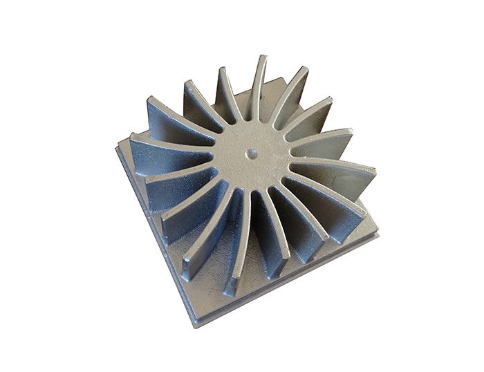
The production cost is controllable, and the cooling wing cannot be made thin, so it is difficult to maximize the heat dissipation area. Adc10 and ADC12 are commonly used as die-casting materials for LED PCB Heatsink.

Extrusion aluminum heatsink
Extruded Aluminum Heatsink- FastPCBunion.com
Extrusion Aluminum PCB

The liquid aluminum is extruded by a fixed die, and then the bar is machined and cut into the required shape of heatsink. This kind of heatsink has a high cost in later processing. The extruded aluminum heatsink is shown in the figure. The cooling wing can be made many very thin, and the heat dissipation area can be expanded to the largest extent. When the cooling wing works, it automatically forms the air convection to diffuse heat, and has good heat dissipation effect. The commonly used materials are Al6061 and al6063.

Stamping aluminum heatsink
Stamping Aluminum Heatsink - FastPCBunion.com
Stamping Aluminum Heatsink

The steel and aluminum alloy plates are pressed and pulled up by punch and die to make them become cup and barrel type heatsinks. The inner periphery of the heatsink formed by stamping is smooth, and the heat dissipation area is limited due to no wings. The commonly used aluminum alloy materials are 5052, 6061 and 6063. Stamping heatsink is a low-cost production method because of its low quality and high material utilization.

The heat conduction of stamping aluminum alloy heatsink is satisfactory, and it is suitable for blocking switch constant current power supply. As for the non barrier switch constant current power supply, it needs to go through the structure design of lamps and lanterns, and do a good job in the isolation of AC and DC, high voltage and low voltage power supply before it can pass CE or UL certification.

Plastic cladding aluminum heatsink
Plastic Cladding Aluminum Headsink - FastPCBunion.com
Plastic Cladding Aluminum Headsink

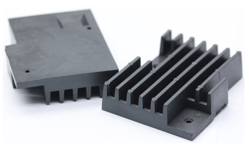
It is a kind of heat conduction plastic shell aluminum core heatsink. The thermal conductive plastic and aluminum heat dissipation core are molded on the injection molding machine at one time. The aluminum heat dissipation core is an embedded part, which needs to be machined in advance. The heat of LED lamp bead is quickly transferred to thermal conductive plastic through aluminum heat dissipation core. Thermal conductive plastic uses its multi wings to form air convection heat dissipation, and uses its surface to radiate part of the heat.

Plastic coated aluminum heatsink generally uses the original color of thermal conductive plastic white and black, and the radiation heat dissipation effect of plastic clad aluminum heatsink with black plastic is better. Thermal conductive plastic is a kind of thermoplastic material. The fluidity, density, resistance and strength of the material are easy to be molded by injection molding. It has good thermal shock resistance and excellent insulation function. The radiation coefficient of thermal conductive plastics is better than that of common metal materials. The density of thermal conductive plastic is 40% less than that of die-casting aluminum and ceramics. For heatsinks of the same shape, the amount of plastic coated aluminum can be reduced by nearly one third; compared with all aluminum heatsink, the processing cost is low, the processing cycle is short, and the processing temperature is low; the products are not fragile; the injection molding machine provided by customers can design and produce lamps with different shapes. Plastic coated aluminum heatsink has good insulation function and is easy to pass the safety regulations.

High thermal conductivity plastic heatsink
High thermal conductivity plastic heatsink​ - FastPCBunion.com
High thermal conductivity plastic heatsink​

High thermal conductivity plastic heatsink is a kind of all plastic heatsink. Its thermal conductivity is dozens of times higher than that of ordinary plastics, up to 2-9w / MK, which has excellent heat conduction and radiation capacity. It can be used in various power lamps and lanterns, and can be widely used in all kinds of LED lamps from 1W to 200W.

The withstand voltage grade of high thermal conductive plastic can reach 6000V AC, which is suitable for non isolated switch constant current power supply and high voltage linear constant current power supply of hvled. This kind of LED lighting lamp is easy to pass the CE, TUV, UL and other strict safety inspection. High voltage (VF = 35-280vdc) and low current (if = 20-60ma) are adopted for hvled, so the heat of hvled lamp bead plate is reduced. Traditional injection molding and extrusion machines can be used for high thermal conductivity plastic heatsink. High finish, high finish. Greatly improve the efficiency of production, high flexibility of modeling design, can give full play to the designer’s design concept. It has no pollution of starch and plastic, no pollution in the process of production.

The PLA molecules of high thermal conductivity plastic heatsink are densely packed with nano metal ions, which can move rapidly at high temperature and increase the thermal radiation energy. Its activity is better than that of metal heatsink. High thermal conductivity plastic heatsink is resistant to high temperature, does not crack and deform at 150 ℃ for five hours. With the application of high voltage linear constant current IC driving scheme, it does not need electrolytic capacitor and large volume inductance, and greatly improves the life of LED whole lamp. The non isolated power supply scheme has high efficiency and low cost. It is especially suitable for the application of fluorescent light and high-power mining light.

High thermal conductivity plastic heatsink can be designed with many precision fins. The fins can be made into many thin ones, and the heat dissipation area can be expanded to the largest extent. When the heat dissipation wing works, the air convection will be formed automatically to diffuse heat, and the heat dissipation effect is good. The heat of SMD LED bead is directly transferred to the heat dissipation wing through high thermal conductivity plastic, which can quickly dissipate heat through air convection and surface radiation.

The density of high thermal conductive plastic heatsink is lighter than that of aluminum. The density of aluminum is 2700 kg / m ⊃ 3; while the density of plastic is 1420 kg / m ⊃ 3;, which is almost half of that of aluminum. Therefore, for heatsinks of the same shape, the weight of plastic heatsinks is only half of that of aluminum. Moreover, the processing is simple, and the molding cycle can be shortened by 20-50%. Therefore, compared with the aluminum heatsink, high thermal conductivity plastic heatsink also has a certain cost advantage.

Appendix

Thermal conductivity of common solid materials

MaterialTemperature, ℃Thermal conductivity λ, w / m · K MaterialTemperature, ℃Thermal conductivity λ, w / m · K MaterialTemperature, ℃Thermal conductivity λ, w / m · K
aluminum300230 Insulating brick0~1000.12~0.21 graphite0151
cadmium1894 Building brick200.69 Asbestos board500.17
copper100377 Fluffy blanket0~1000.047 asbestos0~1000.15
Wrought iron1861 Cotton wool300.05 concrete0~1001.28
cast iron5348 Glass301.09 refractory bricks 1.04
lead10033 mica500.43 TDD (XPS board) thermal insulation integrated board250.028
nickel10057 Hard rubber00.15 TDD (vacuum insulation) integrated board250.006
silver100412 Sawdust200.052 TDD vacuum insulation board250.006
Steel (1% C)1845 cork300.043 ABS0.25
Marine metals30113 Glass wool0.041 stainless steel2016
bronze 189 85% MgO0.07 TDD (rock wool) insulation integrated board700.04